Lab 6 Orientation Control
The purpose of this lab was to implement angular PID/orientation control of our robot such that it can correct itself after a disturbance to the system.
Prelab
Bluetooth
Please reference my Lab 5 report for a breakdown of my debugging and bluetooth communication, as I followed the same process here.
To handle the IMU, I just added new cases and a new set of boolean flags to check whether angular PID should be on or off. T make my life easier, I also added cases that would allow me to change my setpoint, similar to how I change my gain, by passing in and parsing a string. I also modified my notification handler to accept the PWM and IMU values in the angular case, so that if both feedback loops run at once, I can still get all the data. If the flag PID_ANG_ON was set to true and the bluetooth was connected, then my PID function would be called repeatedly. An overview of my different cases:
- Start Linear PID
- Stop Linear PID
- Start Angular PID
- Stop Angular PID
- Change Linear Setpoint
- Change Angular Setpoint
- Change Linear Gain
- Change Angular Gain
- Change Max Speed
- Send Data
P Control
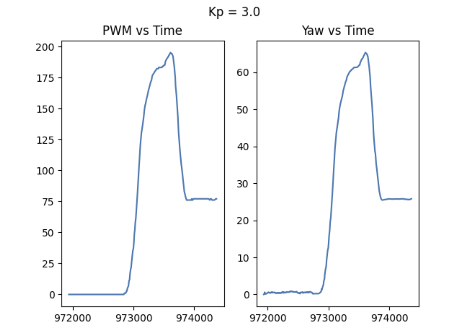
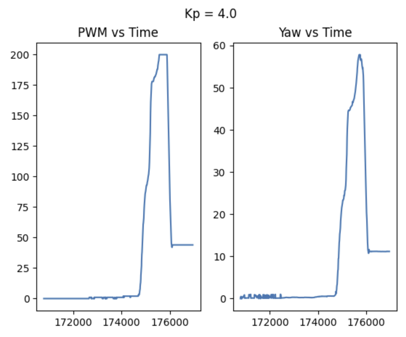
Similar to linear PID, I started with just a proportional controller, meaning that my pwm output was just based on error and the gain value that I tuned:
                                error_ang = theta - targetTheta;

                                float Pterm = Kp_ang * error_ang;
With just P control, I noticed two main issues.
- I consistently had a steady state error of about 10 degrees. Even as I kept increasing Kp, the error would only decrease so much before the robot would just jitter around (pwm too low; I ended up saying that if the pwm was any lower than 10% of max speed, that the robot should just remain stationary.).
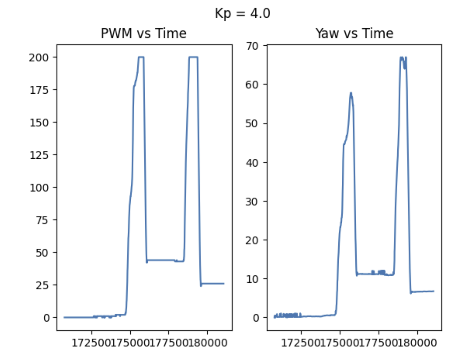
- Too large a gain just ended up in large overshoot (which is expected, based on how PID works).
Data comparisons of a few different cases are shown below, as well as some videos.
These observations inspired me to add an integral controller to try and decrease my steady state error.
Carpet Woes :<
Most of my initial P-tuning happened on carpet. However since my testing involve disturbing the robot from a static position, I found it a lot harder to reliably tune a controller on the rough surface. I think that the coefficient of friction (both static and kinetic, but especially the former) was just too high on the carpet to accurately tune my controller for both tiled and carpeted scenarios. The steady state error was often much higher than it was for tile, but increasing the gain would make it too high for tiled surfaces. Some videos are shown below, but I ultimately just chose to test on campus instead. An example of a graph with some large overshoot is seen here- the video unfortunately does not match.
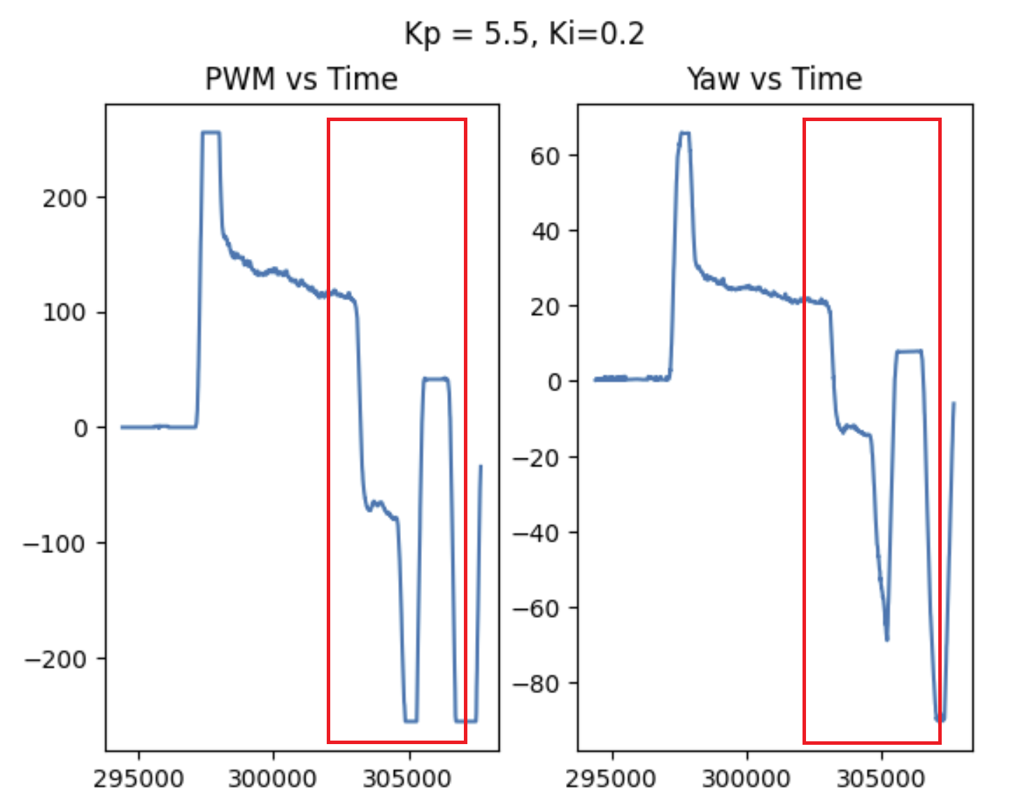
PI Control
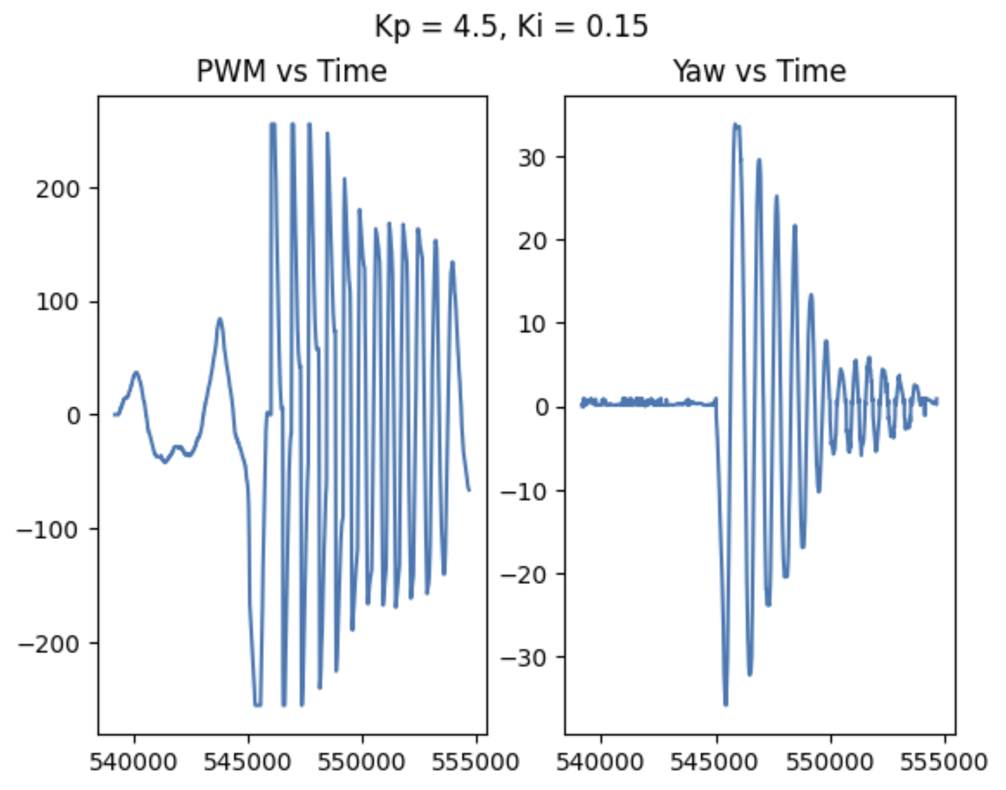
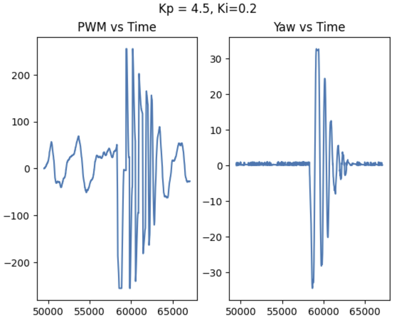
Next, I added an integral controller to try and get rid of steady state error. I tried a few different integral gains, and settled in the range of: 0.2, 0.25, and 0.15. At any lower integral gain, I did not see an effect. But any higher, and there were just too many oscillations and the robot would not quite settle. It ultimately improved my steady state error, but added so much extra oscillation that I decided to add a derivative controller to try and combat this.
                            float dt = 35; //100 ms
                            sumError_ang = sumError_ang + error_ang*dt;

                            float Iterm = Ki_ang * sumError_ang;
                            if(Iterm > 150)
                                Iterm = 150;
                            else if(Iterm < -150)
                                Iterm = -150;
Integrator Windup (5000 Level)
I also took integrator windup into account, since I did not want my controller to saturate. I monitored the contribution from my Iterm over time for a few runs and ended up capping my integral term at +/-150 based on the possible control outputs. At a control gain of 0.25, this means the I control can contribute no more than 30 PWM.
PID Control
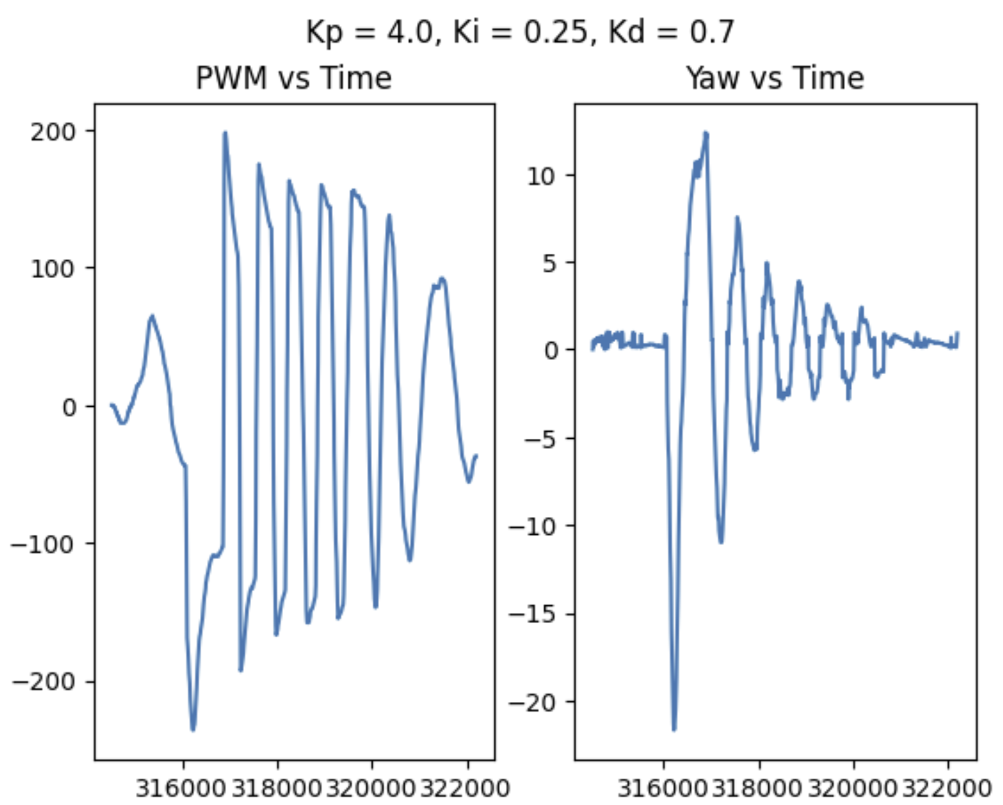
To try and reduce oscillations, I then added a derivative control. Any value between 0.5 and 0.7 seemed to improve performance, but the higher the derivative gain value, the faster and thus better the performance of the controller was overall. My most successful/smooth run had Kp = 4.0, Ki = 0.25 and kd = 0.7. It is worth noting that after adding derivative gain I actually decreased the proportional gain a bit to decrease the initial overshoot. The controller itself is still slower than I would like it to be, so some additional tuning may be needed. One issue that still needs to be addressed is derivative kick if the setpoint is to be changed quickly, such as in the case of a fast turn followed by straight driving; if I was to try and fix this, I would try to track the setpoint over time, such that the D term was based on rate of change in setpoint as well as error...
In my testing, though, I did not notice derivative kick, likely because I almost always started from a static position. Regardless, I was satisfied with the performance of my controller once I had a full PID loop. Where my linear control was fine with just PI, derivative control played a large role in orientation control. Some results, as well as the full function, can be seen below. Adding a derivative term did slow down my overall settling time a bit, though, which I did not like.

Speed Discussion
My controller ran approximately as fast as the IMU sensor itself. Unlike the linear PID which took about 100 ms between iterations, the angular PID calculated new values every 40ms.
Discussion
Ultimately, I found it harder to tune angular control than linear control. I actually needed deriviative control this time, and experienced a slower settling time and larger oscillations, still. I am hoping to make my controller smoother in the future. I would also like to make the time constant of the system much smaller/make the overall response faster. Proportional control was very fast, but always undershot. Adding integral control helpe dget rid of steady state error, but with a lot of dancing and oscillating. Derivative control eased up the oscillations, but my settling time is still high. I need to keep working on making my system faster for when we do stunts. Perhaps the Kalman filter/prediction methods will help with this...
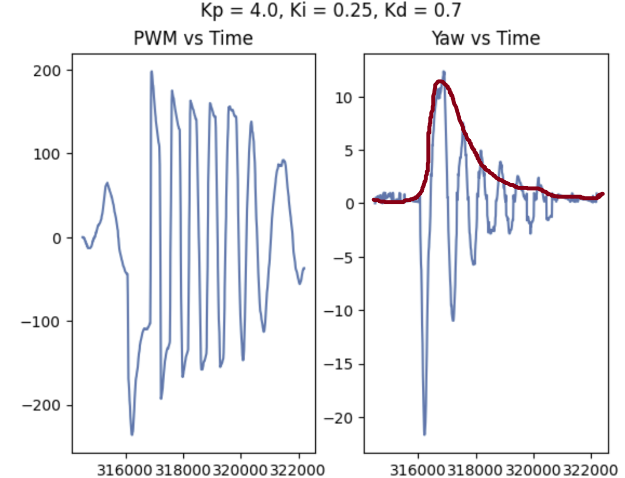
My desired performance would follow the peaks of the yaw values above without the extra oscillations :(